?

  • RFL 9508
RFL 9508 DSP Powerline Carrier System

Product Description

The RFL 9508 DSP Powerline Carrier System is a highly integrated and state of the art PLC terminal which incorporates Digital Signal Processing technology (DSP) to increase reliability and flexibility, while reducing physical size. Furthermore, the mechanical arrangement has been simplified for easier installation and maintenance.

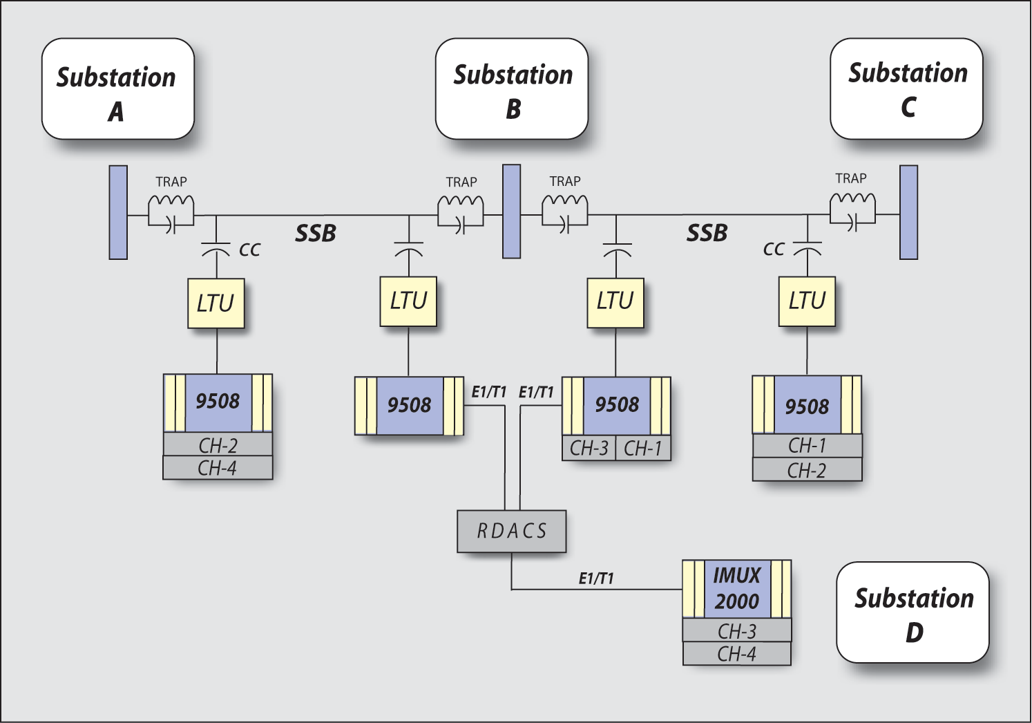
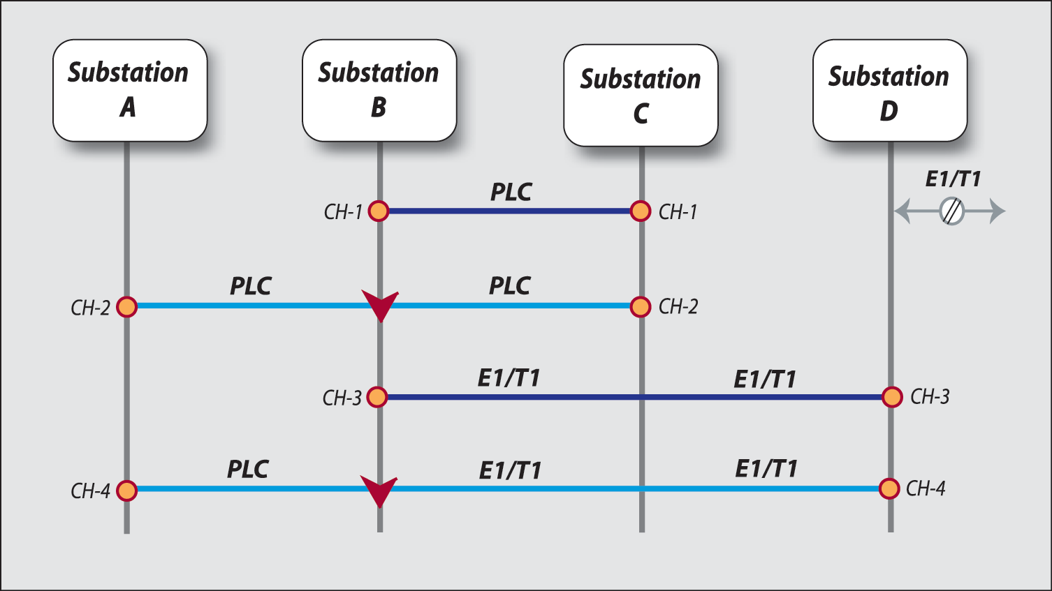
These terminals offer a choice of two power output levels, and a wide range of options which include the choice of PLC, E1 or T1. Plug-in teleprotection modules are available to complete an integrated communication system design.

All channels are capable of Drop and Insert operation at the analog or digital T1/E1 level. These features make for a unique product that is ultimately flexible.

The frequency range is 20 kHz to 500 kHz. Single Side Band (SSB) modulation is used for the RFL 9508 where the use of the spectrum is optimized with high quality adjacent channel selectivity. Idle channel noise, cross-talk and spurious outputs are minimized and high frequency stability over the specified temperature range is achieved.

The equipment is designed to operate in the harsh environment of electric utility substations and is based, in part, on the successful and proven RFL IMUX 2000 T1/E1 multiplexer family of products.

An integrated orderwire service channel is included in the standard system. It features an adjustable volume control and audible ARD tone at the far end when the handset is taken off the hook at the near end.

Key Features and Benefits

  • Interconnection between a Power Line Carrier and any existing or new T1/E1 Network.
  • IEC60495 and IEC60834-1 standards exceeded.
  • Programmable for 2.5 kHz or 4 kHz operation.
  • AF and RF functionality 100% programmable through a Windows® Interface.
  • 50 or 100 Watt PEP output power.
  • Up to 8 independent commands of integrated transfer trip.
  • 20 kHz - 500 kHz frequency range with no components to change in the field.

Teleprotection Electrical Specifications

Optically Isolated Inputs:

  • Operating Voltage Range:
    • 48 Vdc     38-60 Vdc
    • 125 Vdc     88-150 Vdc
    • 250 Vdc     200-280 Vdc
  • Input threshold 1/2 normal station battery.

Solid-State Outputs:

  • Maximum continuous output current      1 A
  • Minimum output current     20 mA
  • Maximum open circuit voltage     280 Vdc
  • Maximum turn on delay     100 µs

Optional Relay Outputs:

  • Maximum continuous output current 2 A (inductive)
  • Maximum surge current (100ms)     30 A
  • Maximum breaking current     1 A (resistive)
  • Maximum open circuit voltage     280Vdc
  • Maximum operate time     5 ms
  • ESD Withstand     IEC-610004-2, ANSI C37.90.3
  • RFl Withstand     IEC-60834, ANSI C37.90.2
  • SWC Withstand     IEC-801-4, ANSI C37.90.1
  • Dielectric Withstand     2500 Vdc per IEC-60255-22-1 and IEC-60834-1

Alarm Relay

  • Output Form     “C” (spdt)
  • Open Circuit Voltage      300 Vdc
    • Current (continuous)      1 A
    • Breaking Current      1 A, Non-inductive

RF Band

  • Frequency range     20 to 500 kHz
  • Full duplex Channels      1, 2, 3, or 4 SSB Channels
  • Channel Bandwidth      2.5 kHz, 4 kHz
  • Selectivity
    • Overall (4 kHz from Bandedge)     = -75 dBmO
    • Channel (0.3 kHz from Bandedge)     = -65 dBmO
  • Impedance      50, 75, 100 or 150 Ohms unbalanced or balanced

AF Band

  • AGC dynamic range      +14 to -26 dB, or + 20dB
  • Background Noise      = -55 dBmOp (IEC60495 recomm)
  • Harmonic Distortion      = -40 dBmO F=400 Hz (IEC 495 recomm)
  • Group Delay      (IEC60495 recomm)
  • Frequency Stability      ± 0.5 Hz at 250 kHz (±2 ppm)
  • Tx Line Filters      Adjustable from 20 to 500 kHz
  • Rx Line Filters      Adjustable from 20 to 500 kHz
  • Minimum sensitivity      -30 dBm

Signaling (Pilot)

  • Frequency      3825 Hz, 3600 or 2385
  • Type of modulation      FSK
  • Frequency shift      ± 30 Hz from channel      center frequency

Environmental Conditions

  • Ambient Temperature Range     -20 to + 65ºC
  • Relative Humidity     0 to 95% non condensing

Weight

  • 50W RFL 9508     38 lbs / 17.3 kg
  • 100W RFL 9508     54 lbs / 24.6 kg
Fig. 1 - a typical application of an RFL 9508 in a system

Fig. 1 - a typical application of an RFL 9508 in a system

This illustrates a power line carrier system with the use of T1 or E1 and digital repeaters. In this case a three-way repeater is depicted. Any combination can be used together in a system to provide excellent communication quality over long distances with many repeats.

Fig. 2 - a typical application of an RFL 9508 in a system

Fig. 2 - a typical application of an RFL 9508 in a system

This illustration also describes baseband repeating. Repeating can also be accomplished by bringing all channels down to audio frequencies and repeating them on this basis, which is the more common practice.

Digital repeaters offer distinct economic and technical advantages over audio repeaters because a digital repeater is made digitally at 1.54 or 2 Mbps; consequently, an audio repeater always requires two repeaters per channel and an increase in the Group Delay.

Available Files

Files Available in the Customer Area

Please visit Operating Manuals or Product/Software Downloads to download relevant files. Requires RFL Customer Account.

Please visit Operating Manuals or Product/Software Downloads to download relevant files. Requires RFL Customer Account.

Files Available in the Customer Area

Network Management Software V9508 10.12

Network Management Software V9508 10.12

RFL 9508 Network Management Software V9508 10.12

This software is used to interrogate and program the RFL 9508 DSP Powerline Carrier system. This ZIP file contains the executable file. Windows 2000 or higher is recommended for use with this software.

Download this software in Product/Software Downloads

RFL Connect

Past CONNECT Course Archives

Download Videos


Online Training Courses In
Networking, Communications,
Protection & Cyber Security

Learn more

Utility industry and electric utility white papers by RFL providing communications and protection solutions to today's challenges, such as migrating data from leased lines.

FEATURED WEBINAR:
Helping Utilities Move Forward in IP Migration

FEATURED SOLUTION:
Multipoint-to-Multipoint Protective Relaying Signaling Using Digital Communications and Built-In Logic

Read our Electric Utility White Papers

Find RFL and Hubbell at an upcoming trade show in your area!

See Upcoming Trade Shows

RFL offers a 24-hour emergency service program that provides specialized service anytime, anywhere in the world. All of RFL's products are engineered and manufactured to the highest-quality standards and are supported by a team of highly trained customer service engineers.

Contact Sales Associate