?

  • IMUX 2000T1E1
IMUX2000T1E1 - multiplexer with common logic redundancy

Product Description

The RFL DS-TT Transfer Trip Module is a bi-directional module designed for use in RFL IMUX 2000 multiplexers. This device is also referred to as the MTS module (Modular Teleprotection System). It transmits and receives data via the T1/E1 serial link and generates and receives trip commands via an I/O adapter module. The RFL DS-TT can support up to four bi-directional transfer trip functions between two IMUX 2000 terminals, or can support DCB (Directional Comparison Blocking) in addition to two transfer trip functions. These terminals can operate point to point between two IMUX 2000 terminal nodes in a network. These terminal nodes can be configured as point-to-point or drop and insert terminals and can be installed at different locations in the network either at adjacent or nonadjacent nodes. The RFL DS-TT module has eight LEDs on the front to indicate the condition of the trip inputs and outputs

TRIP HOLD

This is a timer function which extends the length of time that a trip output is activated after a valid trip condition occurs. For this function to engage, a valid trip condition must exist long enough to satisfy the pre-trip timer. The length of time is programmable independently for each function.

INPUT DE-BOUNCE

This is a timer function which requires that a trip input be present for a certain length of time before a trip command is transmitted. The length of time is not programmable by the user, but is set at the factory to 100µs.

ALARM TIMER

This is a timer function which requires that an alarm condition exists for a certain length of time before an alarm output is generated. The length of time is programmable by the user.

PRE-TRIP TIMER

This is a security timer function set on the Rx Card. It requires that a trip be present for a certain length of time before an output is generated. The length of time is programmable independently for each function. Note that the setting in NMS (Network Management Software) has a propagation delay or offset of 2 ms built in.

The NMS pre-trip timer setting takes into account an approximate 2 ms of processing delay within the module and mux. For example: To cause the Pre-Trip Timer to require 3 continuous milliseconds of Receive Trip Commands before the trip command is accepted, use an NMS pre-trip timer value of 5 ms.

COMMUNICATION CHARACTERISTICS

This module communicates using a single bi-directional DS0. The communication includes programmable addressing to prevent misconnections. One of 32 addresses are selectable.

PROGRAMMABLE LOGIC

Trip hold 3 - 256 ms (1 ms increments)
Output Form normal/invert
Alarm timer (delay) 0 - 2.5 Sec. (10 ms increments)
Pre-trip timer 3 - 16 ms (1 ms increments)
Unblocking Enable/Disable
Sequence of events log 20 records
Operational modes Transfer Trip/DCB

PING PONG

This module is capable of measuring and recording round trip delay. The measurement is run continuously and an alarm is generated if the round trip delay exceeds a user preset value. The frequency of the Ping Pong test is selectable by the user. The resolution of the test is 1 millisecond and the accuracy is 1 millisecond each way.

ENVIRONMENTAL

  • ANSI C37.90 - 1989 (service conditions)
  • Operating temperature - 20°C to + 55°C
  • Storage temperature - 40°C to + 75°C
  • Humidity 95% @ 40°C non-condensing

SWC/ FAST TRANSIENT

  • ANSI C37.90 - 1989 (dielectric)
  • ANSI C37.90.1 - 1989 (SWC & fast transient)

RFI SUSCEPTIBILITY

  • ANSI C37.90.2 35 V/M

OPTICAL INPUT SPECIFICATIONS

Operating voltage range:

  • 48 Vdc 38-60 Vdc
  • 125 Vdc 88-150 Vdc
  • 250 Vdc 200-280 Vdc
  • Input threshold 1/2 nominal station battery

SOLID STATE OUTPUT SPECIFICATIONS

  • Maximum continuous output current 1 Amp
  • Maximum surge current (100 ms) 10 Amps
  • Minimum output current 20 ma
  • Maximum open circuit voltage 280 Vdc

OPTIONAL RELAY OUTPUTS

  • Maximum continuous current 2 A (inductive)
  • Maximum surge current (100 ms) 30 A
  • Maximum breaking current 1 A resistive
  • Maximum open circuit voltage 280 Vdc
  • Maximum operate time 5 ms

ALARM RELAY SPECIFICATIONS

  • Maximum continuous current 1 A (inductive)
  • Maximum breaking current 1 A (resistive)
  • Maximum open circuit voltage 280 Vdc
  • Maximum operate time 10 ms

SYSTEM PERFORMANCE

  • Operate time (back to back) 3 ms (solid state)
  • Dependability (IMUX 2000 in frame) 99.99%
  • Security (10-3 BER on IMUX 2000) 1X10-22

SYSTEM COMPATIBILITY

  • The RFL DS-TT is compatible with all RFL 9001 and IMUX 2000 T1/E1 multiplexers

OPERATING MODES

  • Full duplex (transmit and receive)

POWER CONSUMPTION

  • 2.0 watts maximum
IMAGE

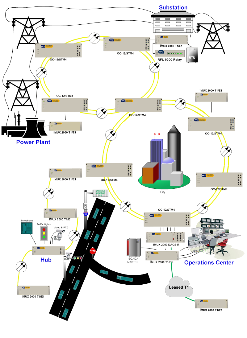
Network Diagram Example

Above is an example of a typical utility / traffic system solution. It is made up of two SONET/SDH rings as the communications backbone. The IMUX 2000 T1/E1 Multiplexers are configured to work in a Point-to-Point, Star and Stand-Alone Linear topology over the SONET/SDH system. The IMUX 2000 carries RTU and phone circuits from several substations to the operations center. It also carries current differential relay data between substations. The IMUX 2000 carries roadside signals, transmission data from vehicle loop detectors, compressed digital video, camera control, toll collection information, status and alarm reporting, voice and data traffic signal controls back to the operations center.

The RFL DS-TT module occupies one module slot in the Main Shelf or Expansion Shelf. The part number for this module is 105720 Each RFL DS-TT module installed in an IMUX 2000 multiplexer requires an I/O Adapter Module. The I/O Adapter Module provides the appropriate connections for the desired interface.

There are eight I/O Adapter Modules that can be used with the RFL DS-TT. These are listed below:

I/O Adapter Module Type Part Number Output Type  
*2 function 48/125V 105770-2 solid state  
*2 function 250V 105770-3 solid state  
*2 function 48/125V 105740-2 relay  
*2 function 250V 105740-3 relay  
4 function 48/125V 105770-4 solid state  
4 function 250V 105770-5 solid state  
4 function 48/125V 105740-4 relay  
4 function 250V 105740-5 relay  

Please visit Operating Manuals or Product/Software Downloads to download relevant files. Requires RFL Customer Account.

Files Available in the Customer Area

Please visit Operating Manuals or Product/Software Downloads to download relevant files. Requires RFL Customer Account.

Files Available in the Customer Area

TRIP HOLD

This is a timer function which extends the length of time that a trip output is activated after a valid trip condition occurs. For this function to engage, a valid trip condition must exist long enough to satisfy the pre-trip timer. The length of time is programmable independently for each function.

INPUT DE-BOUNCE

This is a timer function which requires that a trip input be present for a certain length of time before a trip command is transmitted. The length of time is not programmable by the user, but is set at the factory to 100µs.

ALARM TIMER

This is a timer function which requires that an alarm condition exists for a certain length of time before an alarm output is generated. The length of time is programmable by the user.

PRE-TRIP TIMER

This is a security timer function set on the Rx Card. It requires that a trip be present for a certain length of time before an output is generated. The length of time is programmable independently for each function. Note that the setting in NMS (Network Management Software) has a propagation delay or offset of 2 ms built in.

The NMS pre-trip timer setting takes into account an approximate 2 ms of processing delay within the module and mux. For example: To cause the Pre-Trip Timer to require 3 continuous milliseconds of Receive Trip Commands before the trip command is accepted, use an NMS pre-trip timer value of 5 ms.

COMMUNICATION CHARACTERISTICS

This module communicates using a single bi-directional DS0. The communication includes programmable addressing to prevent misconnections. One of 32 addresses are selectable.

PROGRAMMABLE LOGIC

Trip hold 3 - 256 ms (1 ms increments)
Output Form normal/invert
Alarm timer (delay) 0 - 2.5 Sec. (10 ms increments)
Pre-trip timer 3 - 16 ms (1 ms increments)
Unblocking Enable/Disable
Sequence of events log 20 records
Operational modes Transfer Trip/DCB

PING PONG

This module is capable of measuring and recording round trip delay. The measurement is run continuously and an alarm is generated if the round trip delay exceeds a user preset value. The frequency of the Ping Pong test is selectable by the user. The resolution of the test is 1 millisecond and the accuracy is 1 millisecond each way.

ENVIRONMENTAL

  • ANSI C37.90 - 1989 (service conditions)
  • Operating temperature - 20°C to + 55°C
  • Storage temperature - 40°C to + 75°C
  • Humidity 95% @ 40°C non-condensing

SWC/ FAST TRANSIENT

  • ANSI C37.90 - 1989 (dielectric)
  • ANSI C37.90.1 - 1989 (SWC & fast transient)

RFI SUSCEPTIBILITY

  • ANSI C37.90.2 35 V/M

OPTICAL INPUT SPECIFICATIONS

Operating voltage range:

  • 48 Vdc 38-60 Vdc
  • 125 Vdc 88-150 Vdc
  • 250 Vdc 200-280 Vdc
  • Input threshold 1/2 nominal station battery

SOLID STATE OUTPUT SPECIFICATIONS

  • Maximum continuous output current 1 Amp
  • Maximum surge current (100 ms) 10 Amps
  • Minimum output current 20 ma
  • Maximum open circuit voltage 280 Vdc

OPTIONAL RELAY OUTPUTS

  • Maximum continuous current 2 A (inductive)
  • Maximum surge current (100 ms) 30 A
  • Maximum breaking current 1 A resistive
  • Maximum open circuit voltage 280 Vdc
  • Maximum operate time 5 ms

ALARM RELAY SPECIFICATIONS

  • Maximum continuous current 1 A (inductive)
  • Maximum breaking current 1 A (resistive)
  • Maximum open circuit voltage 280 Vdc
  • Maximum operate time 10 ms

SYSTEM PERFORMANCE

  • Operate time (back to back) 3 ms (solid state)
  • Dependability (IMUX 2000 in frame) 99.99%
  • Security (10-3 BER on IMUX 2000) 1X10-22

SYSTEM COMPATIBILITY

  • The RFL DS-TT is compatible with all RFL 9001 and IMUX 2000 T1/E1 multiplexers

OPERATING MODES

  • Full duplex (transmit and receive)

POWER CONSUMPTION

  • 2.0 watts maximum
IMAGE

Network Diagram Example

Above is an example of a typical utility / traffic system solution. It is made up of two SONET/SDH rings as the communications backbone. The IMUX 2000 T1/E1 Multiplexers are configured to work in a Point-to-Point, Star and Stand-Alone Linear topology over the SONET/SDH system. The IMUX 2000 carries RTU and phone circuits from several substations to the operations center. It also carries current differential relay data between substations. The IMUX 2000 carries roadside signals, transmission data from vehicle loop detectors, compressed digital video, camera control, toll collection information, status and alarm reporting, voice and data traffic signal controls back to the operations center.

The RFL DS-TT module occupies one module slot in the Main Shelf or Expansion Shelf. The part number for this module is 105720 Each RFL DS-TT module installed in an IMUX 2000 multiplexer requires an I/O Adapter Module. The I/O Adapter Module provides the appropriate connections for the desired interface.

There are eight I/O Adapter Modules that can be used with the RFL DS-TT. These are listed below:

I/O Adapter Module Type Part Number Output Type  
*2 function 48/125V 105770-2 solid state  
*2 function 250V 105770-3 solid state  
*2 function 48/125V 105740-2 relay  
*2 function 250V 105740-3 relay  
4 function 48/125V 105770-4 solid state  
4 function 250V 105770-5 solid state  
4 function 48/125V 105740-4 relay  
4 function 250V 105740-5 relay  

Please visit Operating Manuals or Product/Software Downloads to download relevant files. Requires RFL Customer Account.

Files Available in the Customer Area

Please visit Operating Manuals or Product/Software Downloads to download relevant files. Requires RFL Customer Account.

Files Available in the Customer Area

RFL Connect

Past CONNECT Course Archives

Download Videos


Online Training Courses In
Networking, Communications,
Protection & Cyber Security

Learn more

Utility industry and electric utility white papers by RFL providing communications and protection solutions to today's challenges, such as migrating data from leased lines.

FEATURED WEBINAR:
Helping Utilities Move Forward in IP Migration

FEATURED SOLUTION:
Multipoint-to-Multipoint Protective Relaying Signaling Using Digital Communications and Built-In Logic

Read our Electric Utility White Papers

Find RFL and Hubbell at an upcoming trade show in your area!

See Upcoming Trade Shows

RFL offers a 24-hour emergency service program that provides specialized service anytime, anywhere in the world. All of RFL's products are engineered and manufactured to the highest-quality standards and are supported by a team of highly trained customer service engineers.

Contact Sales Associate